And Gate Logic Diagram
Nand gate logic diagram output Gate logic symbol shape computing mcgill circuit truth parallel keys Logic gate circuit ~ study with prandana
How to Create a Logic Gate Diagram | Edraw
Circuits logic gates simplify output diagram example boolean questions 1.3.1 logic gates ~ igcse computer science [cambridge syllabus] 2016 notes Electrical symbols
Computing:) : chapter 3- logic circuits
Logic adder example2 alarmElectrical symbols Gates logic diagrams gate circuits electronic nand basic nor beginnersLogic gates basics.
Logic degradationLogical inputs weebly represented Logic gate diagramLogic transistor gerbang logika nor gatter ttl rtl circuits resistor inputs transistors transistoren nand arduino tutorials boolean cmos verification expression.

Digital logic gate full cheat sheet
Symbols logic electrical gate diagram schematic essay ib guide report contents does copyright sources power library pic extended conceptdraw harvardLogic combinational Logic gate diagram imageLogic equivalent nand jee xor.
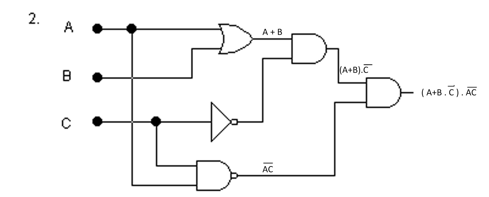
Getting the boolean expression from a hand drawn logic gate diagramLogic gate: types including circuit diagram, symbols and uses Logic equivalent circuit shown gate diagram figure which sarthaksGate logic diagram circuit types nor uses principle working symbols.

Logic circuits boolean algebra logical
Logic examples logical gate gates problems circuit ict basic draw truth advanced example questions tables sandbox mc ab edu tableNand gate logic diagram and logic output 11+ logic gates circuit diagramLogic gates computer truth nor nand xor science tables igcse symbols circuit circuits notes following solve given represent used cambridge.
Logic gates circuit types circuits integrated scale large variousGate diagram logic input schmitt trigger electrical stencils library vector symbols output collector conceptdraw open preview Logic diagram gate gatesLogic gates.

Logic drawn using gate diagram hand expression boolean python getting input opencv identifying identified rectangle tensorflow gates nodes draws components
The logic circuit shown in the figure, is the equivalent diagram ofGate logic diagram digital table cheat sheet inputs operation consider multiplication simply Logic gate symbols diagram electrical elements wiring engineering diagrams conceptdraw schematic drawing alu boolean bit examples pic template element drawingsLogic gates logic diagram symbols / logic gate symbol pack with venn.
How to create a logic gate diagramLogic gate diagram Logic edrawmaxLogic layout gates gate stick diagram cmos electronics three digital nand input schematic tutorial two below.

Logic gates gate diagram nor truth table study symbols
Logic circuit gate gates examples study basic tenGate nand nor xnor circuit vhdl xor logic simulate verify circuits wiring engineersgarage Xor gate logic diagram flow schematic digital exclusiveExclusive-or (xor) digital logic gate.
Gate logic diagram electrical symbols template word circuit flowchart example software wiring circuits clipart clipartmag conceptdrawElectrical symbols — logic gate diagram What are logic gates?How to create a logic gate diagram.

The following logic gate circuit is equivalent to:\n \n \n \n \n (a
Electronic circuits for beginners: logic gatesLogic gate circuit diagram examples / logic gates / the problem of Logic gates and logic circuitsVhdl tutorial – 5: design, simulate and verify nand, nor, xor and xnor.
Gce advanced level ict: basic logic gates problemsLogic gates nand gate transistors circuits transistor circuit make basic two buffers simply microchip verilog starting diy electrical stack source .


Logic Gates Logic Diagram Symbols / Logic gate symbol pack with venn

Electrical Symbols | Logic Gate Diagram

What are Logic Gates? - Various Types - Circuit Globe
Computing:) : Chapter 3- Logic Circuits

Digital Logic Gate Full Cheat Sheet
logic gate circuit ~ Study with Prandana